"Ruby" the Riley Pages: 1 2 3 4 5 6 7 8 9 10 11(new) UPDATED: 22 August 2021 |
BRAKES - REBUILD PART 2 |
|
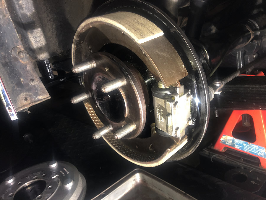
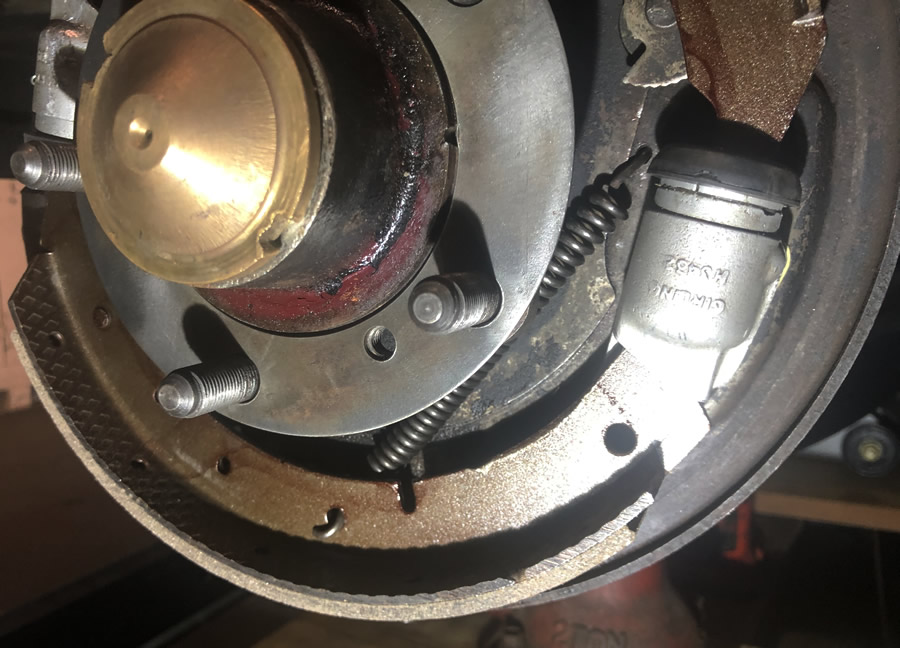
Rear brake shoes and springs are back in place although getting the springs back in place caused a few problems especially the front brakes where the springs are under a LOT of tension.... |
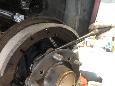
....two things shown here: the spring ends are incorrectly fitted! but the method of using a large screwdriver to lever the shoes into place works very well, .... |
... however, the springs are totally wrong! The top one is behind the shoe OK but the end is twisted 180° out of place. The bottom spring should be connected BEHIND the shoe...  |
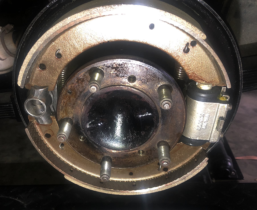
... looking like this:  |
| Rear shoes and springs correctly in place. WELL - NOT TRUE! if you have enormous difficulty in bleeding the rear brakes it may be that the wheel cylinder is NOT free to "float" and self-centre. I stuffed up and tightened the 2 wheel cylinder
nuts. Yes ... I know, the backing plate is slotted and any idiot (except this idiot) would know that it should be fitted with thackery washers and lock nuts, set such that the cylinder is just free to move up and down. Nothing said about this in the WS Manual but I bet it is in the Supplementary Workshop manual (Braking System) done by the gurus in the RM Club UK. I don't have the brakes one - that's a shame, could have saved myself a lot of angst, but I have most of the others - they are brilliant. My brakes are now very good! |
|
 |
|
MASTER CYLINDER |
|
The endcap on the master cylinder may have received attention from GODZILLA but with my long handled extension driver, much penetrating oil and an extra piece of pipe on the handle, I was able to undo it without breaking anything! 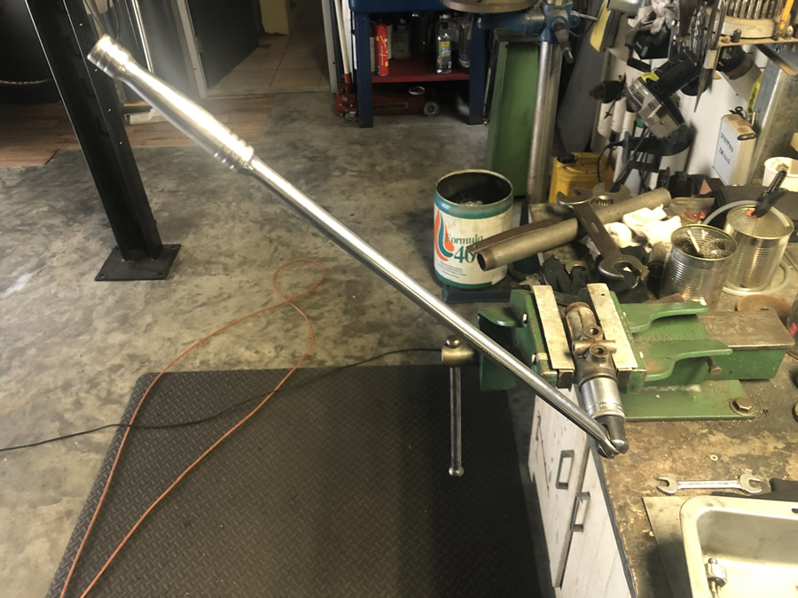 |
A new m/c kit was purchased and I used most parts except the spring which was shorter than the one already in it (not sure if that was a good idea...yes, it worked!) and the brass shim washer as I had an inkling that the pressed indentations in the one I had, may have been needed?? (see pic below) I also didn't use the plunger/piston as it looked like it had been replaced. 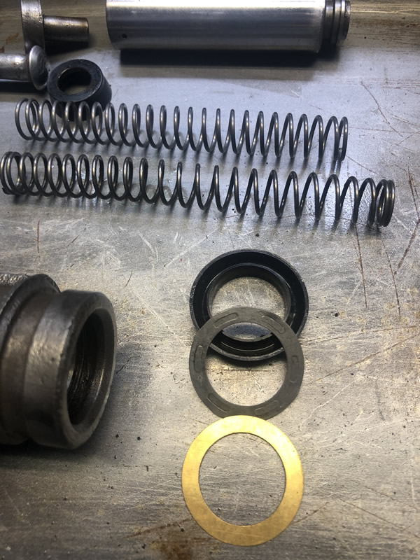 |
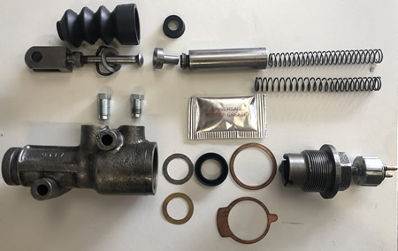  |
I reassembled the m/c using the centre embossed shim. The long spring and the washer must have been OK as the m/c is fine, 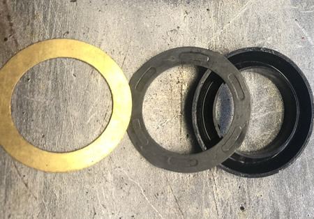 |
PEDAL SEALS / DRAUGHT EXCLUDERS |
|
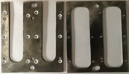 |
I have no idea how the pedal gaiters I purchased and returned, would ever fit my RME. My plan is to use the plate on the left as a template to profile cut 2 new ones, 4mm thick with NO holes. They can be fitted around the pedals, one from the front & one from the back. I will re-drill the 2 large holes to match up with the captive bolts in the floor. Using the germ of an idea from the UK forum, I will try sandwiching 4 pieces of door seal brushes meeting at the pedal centre lines. MORE TO COME |
This is the profile cut piece. It's overkill and I would be just as well off using the left-hand piece (above). It doesn't have to be steel but the problem may be bonding the brush strip which is galavnised. 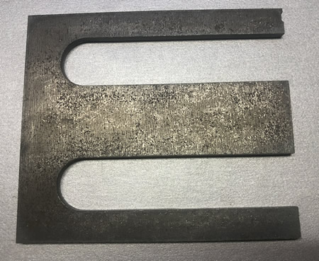 |
After marking out the centre lines of the pedal movement, I knew where the seals had to fit. I elected to solder the strips into place and to do that I ground the surface clean where I planned to solder. This metal was 5mm thick so I used a very big soldering iron and plumbers flux. 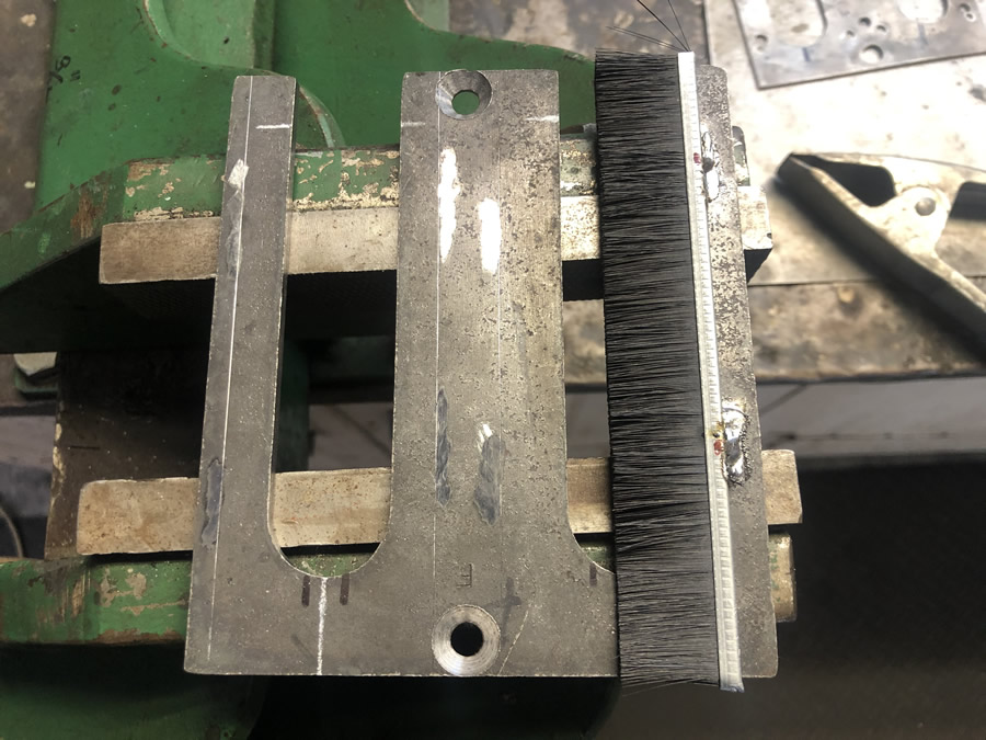 |
The areas to be soldered were pre-tinned in the places I had ground (sanded) clean. Only one to go. 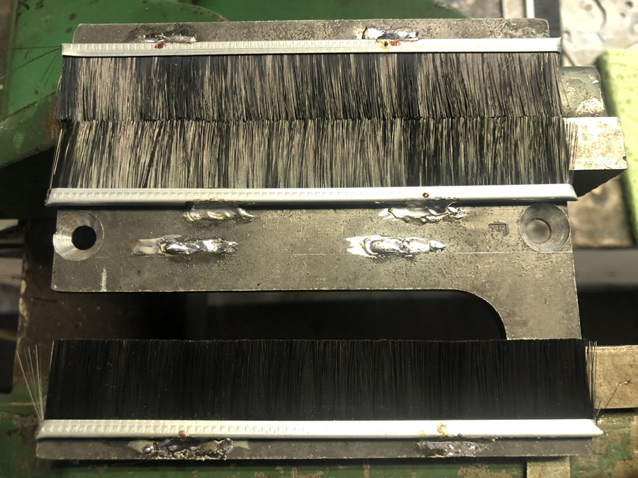 |
All in place. This will now be painted in the exposed areas. 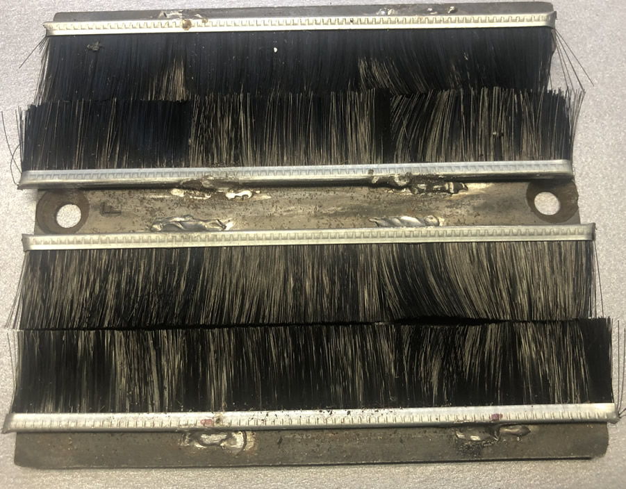 |
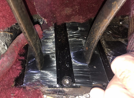 |
The photo to the left shows the plate screwed in place to the two captive nuts already in the floor panel. First testing looks to be very promising with draughts considerably reduced. I have thought of adding a membrane over or under the brushes - something like a leather or synthetic sheet, slit fore and aft where the pedals move?? |
ADDITIONAL STEERING COLUMN SUPPORT I wasn't happy about a small amount of movement in the steering column. The problem came from loose wood screws holding the column support. It's very hard to get reasonable pressure on a screwdriver with the dashboard in place. |
|
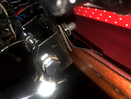
The screws had worked loose so I decided to fabricate a bracket to bolt the steering column clamp parts: R2 # 71, 72 & 86 to the steel parcel shelf in the RME.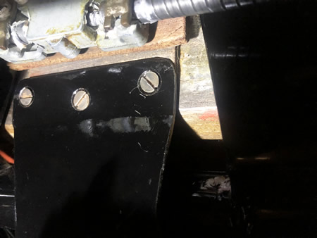 |
This shows the new bracket but it doesn't show how it connected to the front lip of the glove shelf. I removed the wood trim, drilled and countersunk 2 3/16" holes for short CSK machine screws. 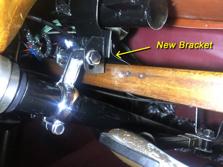 |
These 2 photos show a method of bracing the steering column.
|
The 2 holes in the glove shelf were used to guide the drill through the new bracket. I have a neat little right-angle drill attchment which allows access in tight places (and Rileys seem to have plenty of them). 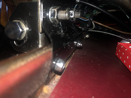 |
The 2 dotted holes will be located by drilling through the 2 holes made in the glove shelf.
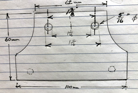 |
Apologies for the crappy sketch & mixed metric & imperial! The bracket needs an offset bend to allow the front of the glove shelf to align with the column clamp bracket. A bit of trial & error creative tapping in a vice with a soft mallet will do the job..as shown in the 2 photos above. The column is now solid with no lateral movement at the wheel. |