Track Feeders and Buses Rick Fletcher - NSW Australia |
|
|||
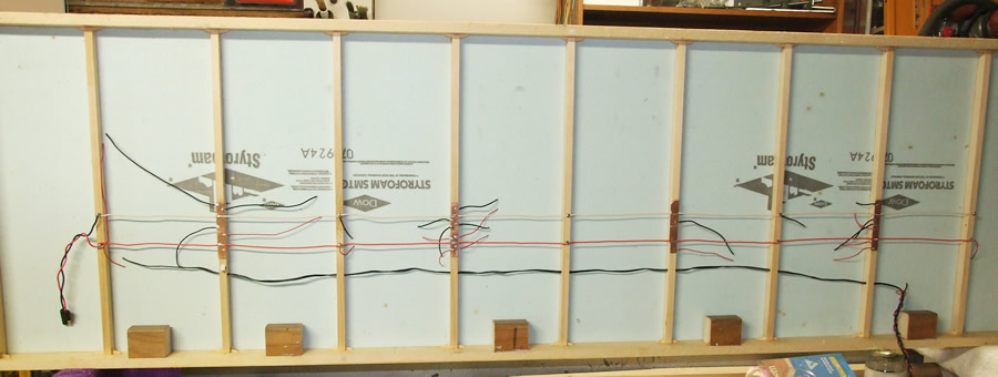
| In the underside view of this little demonstration layout, the Bus wires are the RED and WHITE pair which carry the DCC Bus along the bottom. Tapping into it at several places are DROPPERS or FEEDERS (red and black) to carry the DCC circuit to each piece of track on the top. |
|||
 |
|||
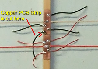
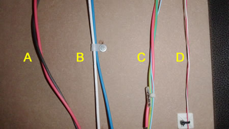
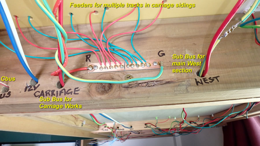
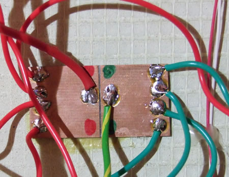
| In this example the bus is connected to a PCB strip in 4 places to simplify connection of the droppers to the bus. | This an underside view of my layout with 4 bus wires in view. A = 12V; (heavy duty stranded copper wire) B = DCC main bus; (as above) C = sub bus (in this case from the main bus to the YARD bus) and D = MERG Can-bus which distributes the electronic data around the layout. Note that it is very thin as it carries low current signals. |
||
 |
 |
||
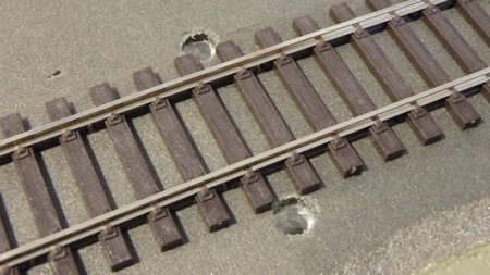
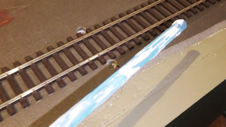
Our problem is to get the track feeders through the baseboard, in this case FOAM, to the Bus underneath. EVERY piece of track must be fed between joiners. There is a special issue with foam. Some sources indicate that the foam can react with the plastic on electrical wiring and cause it to break down. A wooden base board can just be drilled 6mm. |
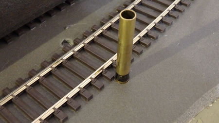
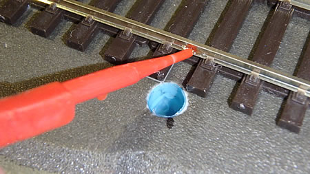
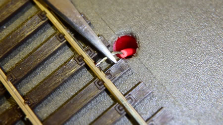
So, after we have drilled the hole in the foam (as shown below with the 6mm K&S brass tube drill still in place) we need to line the hole with an inert material. Note the colour coding - there is no fixed rule but RECORD your code. See the section on DRILLING HOLES IN FOAM for more info. |
||
 |
 |
||
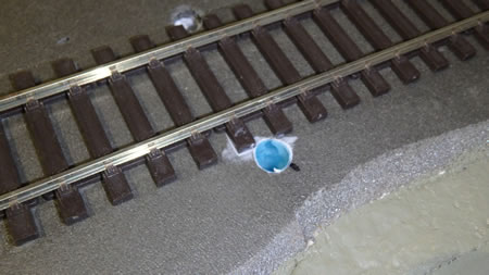
Because this section of my track was using Expanded foam (not recommended) I had to clean the hole out with something that was a loose fit to get rid of all the little white balls of plastic. This not needed in Extruded Polystyrene Foam. See details on foam HERE. |
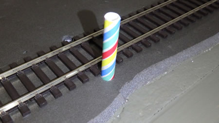
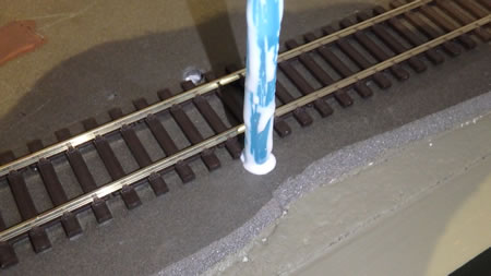
The 6mm hole is an exact fit for a drinking straw. My preference is for the paper straws but they seem to have disappeared on the far South Coast so plastic ones will do. Measure it to be 5 mm longer than the total depth of foam and underlay. |
||
|
 |
||
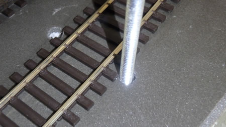
| Coat the straw lightly with some PVA... | ... and slip it into the hole. | ||
 |
 |
||
| Wipe off the excess PVA ... | ...and do the second one. | ||
 |
 |
||
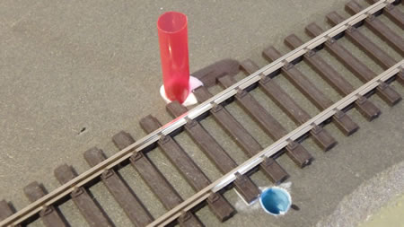
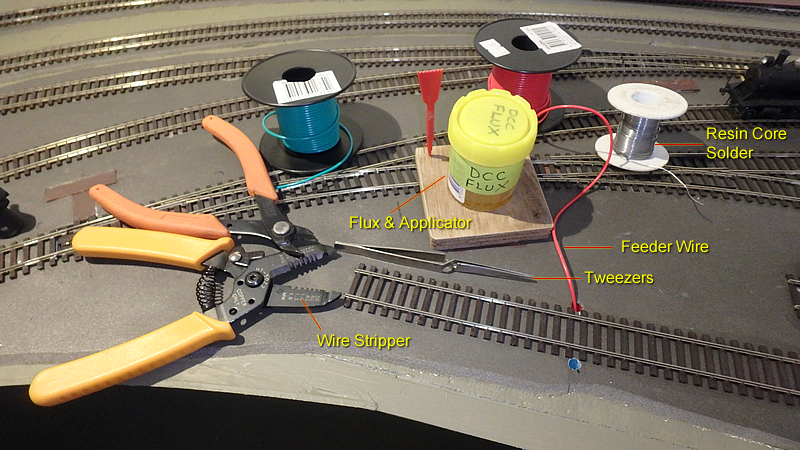
| Now we come to the bit where you need to solder a wire to your track, take it down the feeder hole and connect it to your Bus wiring. Shown below are the tools you will need for the top side. I have a colour code for the droppers - RED is the Right DCC track (or in my case, the REAR track closest to the wall in an around the walls layout). My front rail is fed with GREEN. In a module you just need to be consistent making sure that no swap-overs occur. As can be seen above, I have a main DCC bus which feeds 4 sections - North (Carriage Works), South (Loco), East (Yard) & West (Station). Each section is fed via a STOP LIGHT BULB in series with one feed wire. If there is a SHORT CIRCUIT, the stop light bulb will carry the load and LIGHT UP. See THIS SITE for more info. Or THIS ONE. |
|||
 |
|||
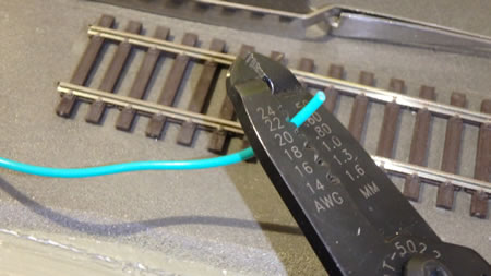
Strip 1cm approx. |
The wire I used was from Jaycar and is sold as Flexible Light Duty Hook Up Wire 13 x 0.12 tinned (WH-3005 green) |
||
 |
 |
||
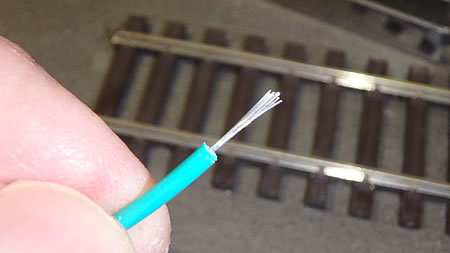
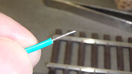
Twist the strands tightly together. |
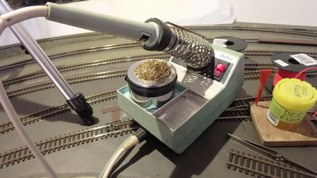
A typical appropriate soldering station. |
||
 |
 |
||
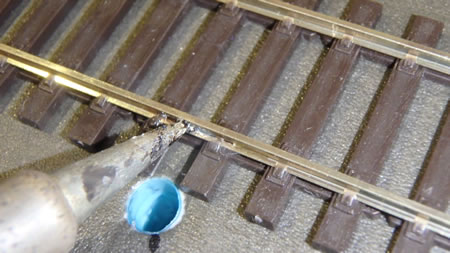
Put a tiny amount of liquid flux on the bottom flange of the rail |
Pick up a tiny amount of solder and tin the bottom flange. |
||
 |
 |
||
This is a better photo of how the tinned flange should appear. |
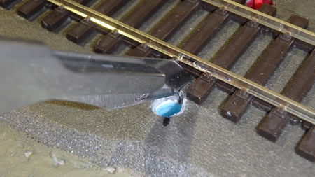
Use a sharp blade to cut a slit in the track bed to allow the feeder to drop straight down from the rail, as in the last photo. |
||
 |
 |
||
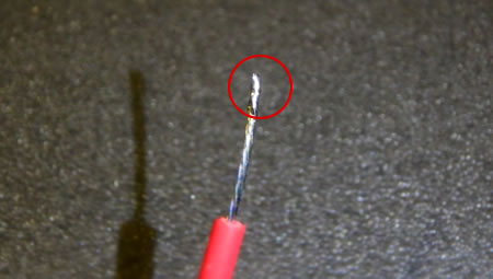
Tin the end of the feeder wire - ideally only the last 2mm! |
This is where the self closing tweezers are handy. Line up the end of the wire with the flange ... |
||
 |
 |
||
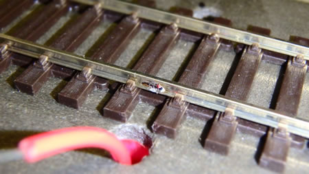
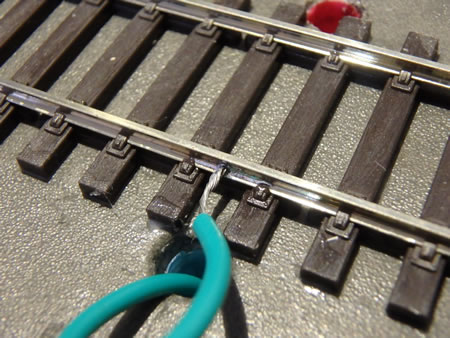
...and try to solder just the tip of the wire to the flange, |
Then push the wire down and into the slit made earlier. |
||
 |
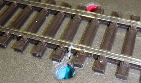 Once the track is painted (weathered) and ballasted the feeder should be invisible. |
||
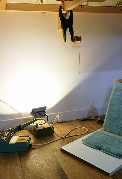
The photo on the right shows some of the kit I use when working under the layout. There is:
|
 |
||
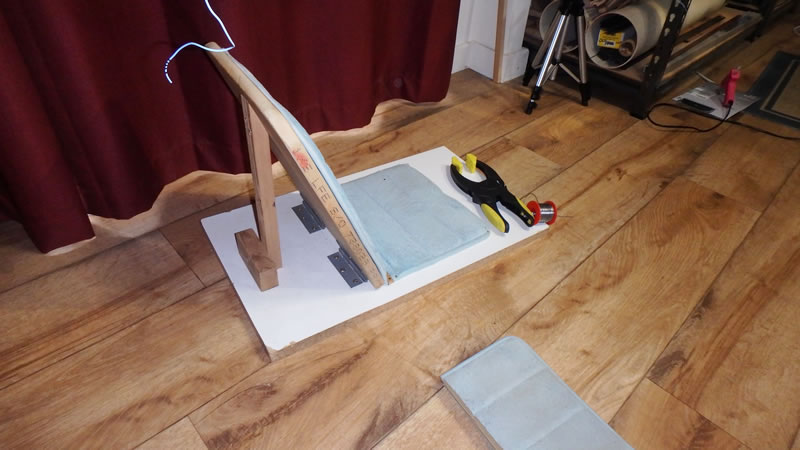
It's a pretty crude seat made out of pine board but it does the job. If I was to build it again I would use thinner timber and perhaps cut some holes to lighten it. The padding is from an old seat cover and the offcut on the floor is my kneeling pad! |
|||
 |
|||
I was a bit reluctant to add the photo below, as the underside of the layout looks like a bit of a "rat's nest". To some extent it is unavoidable when you have to run power to every section of the track right around the layout. It is also compounded by the need to twist the cable pairs and to separate the various cable runs to avoid interference one to the other. In another life I would use the so-called "dead track" approach where locomotives are battery powered, radio controlled DCC. That would eliminate most of the under-layout wiring. Two things to note in this photo:
NOTES ON SOLDERING:
|
|||
 |
|||
I always used to use a damp sponge but I have converted now to a wire scouring pad designed for the job (bought on eBay). The liquid flux I use for soldering to rails is one by DCC Concepts but a flux like Carrs Red works just as well. |
|
||
 |
Whilst this one looks slightly chaotic, it shows a couple of other aspects:
|
||
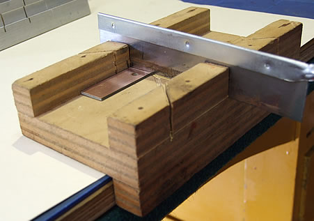
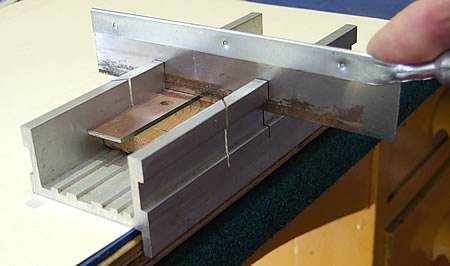
To do a simple divide on the surface of copper clad PCB you can use a home made (left) or purchased mitre box (right). Just make sure that both segments are electrically isolated using a test lead or a multimeter on the Ohms range. |
|||
 |
 |
||