Making Simple PCBs Rick Fletcher - NSW Australia Updated 14 Aug 2016 |
Printed Circuit Boards (PCBs) are possibly a step too far for many railway enthusiasts. However the material lends itself to many simple possibilities.
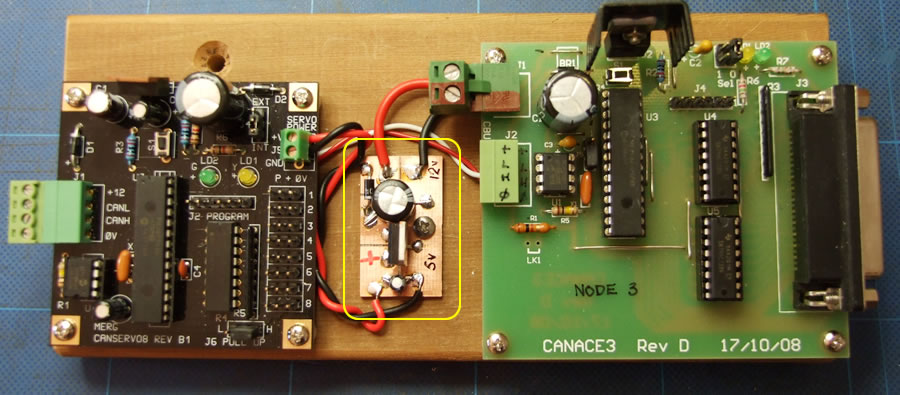
The 3 PCBs below are all based on glass fibre PCBs. The one in the middle is the focus of this article. In simple terms, the one on the left operates up to 8 servos which can be controlled by the one on the right. The latter handles input from switches. |
|
 |
|
| The rest of this article will focus on how to make simple PCBs even more basic than the one outlined above. | |
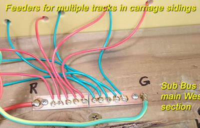
Rather than a Terminal Strip with screws: The PCB on the right is about as simple as you can get (& cheap!) It is divided in 2 discrete parts by making a saw cut through the copper cladding. Each half is a separate part of the circuit. One for the right rail of the DCC supply and the other for the left rail. A couple of screws hold it to wood in this case. It could have been glued (epoxy) to the wood or to the underside of a foam layout with contact cement. 2 screw holes are needed. The copper is cleaned with fine wet & dry or a fibreglass brush. For ease of soldering under the layout, I made 10 small "blobs" of solder. |
 |
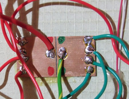 |
This pics below also appeared in the Track Feeder Section Whilst this one looks slightly chaotic, it shows a couple of other aspects:
|
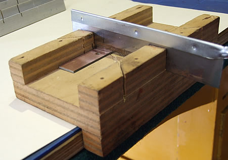
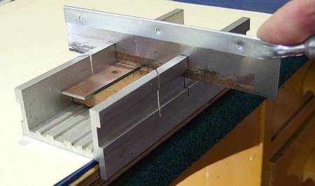
To do a simple divide on the surface of copper clad PCB you can use a home made (left) or purchased mitre box (right).
Just make sure that both segments are electrically isolated using a test lead or a multimeter on the Ohms range. |
|
 |
 |
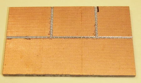
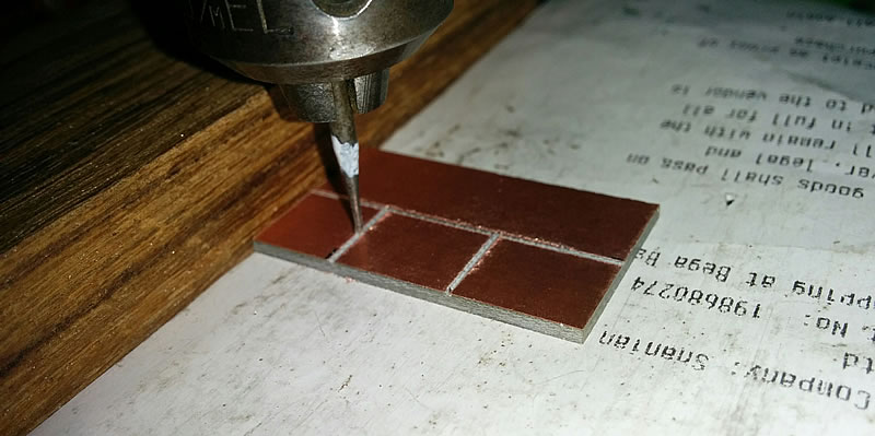
To make the PCB on the right, cutting with a saw, as above, will not work. A cutter such as a dental burr or a "Dremel" engraving cutter such as this one is needed in a rotary tool or drill press. |
 |
The "pads" of copper will form discrete parts, or "pads", of the circuit for this 12V to 5V converter. A slightly more crude approach, but one that will work, is to mark out the pattern with a pen and freehand cut the grooves. The electricity won't mind if the edges are a bit ragged! But check that each area is not shorting to a neighbour with a meter or test lamp. |
|
 |
|
The series of photos below show some basic assembly and soldering tips. The circuit diagram is at the bottom. |
|
NOTES ON SOLDERING:
|
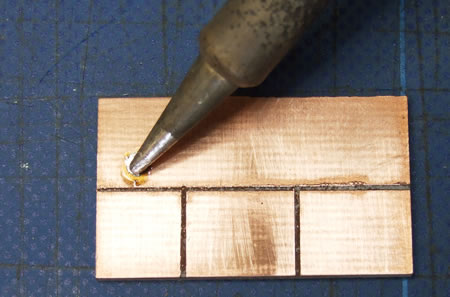 |
A component (an electrolytic capacitor) has the two radial leads separated and cut short such that each goes to a different pad. The component has been held in place with self closing tweezers. The tip of the soldering iron is briefly cleaned - then a tiny amount of solder added to "wet" the tip - apply the tip to the join - feed in some 0.7mm solder. Doing it this way feeds the flux to the joint as well as the solder. A GOOD join should be smooth and have a nice shine to the surface. |
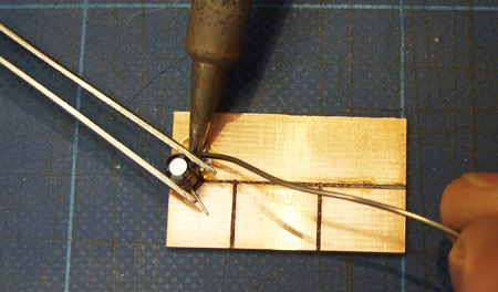 |
Same again on the second leg making sure that each leg is of the component only connects to a separate pad. This method is like working with what are called SMDs (Surface Mount Devices) except that our discrete components are 10s or 100s of times bigger! |
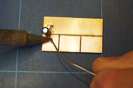 |
The electrolytic capacitor is in position and the Voltage Regulator is being prepared on the right. On a normal PCB the legs would go through holes and be soldered to tracks on the reverse side. In this case the legs are being bent to straddle 3 pads. |
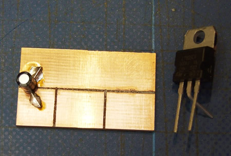 |
And here are all the parts in place on the PCB. To the left is a diode (passes current one way only) which serves to protect the circuit if it is accidentally connected to 12V with the wrong polarity. A larger electrolytic capacitor is behind the diode. Sharp eyes will make out 7805 on the IC - the 5 indicates that the output voltage is 5V. This is the voltage required to operate servos and this board provides that power to the servos. |
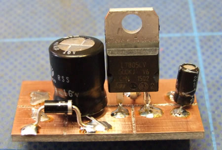 |
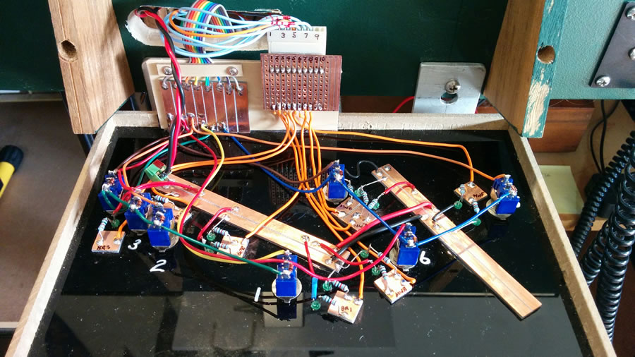
The example below is the rear face of a control panel (see the section on Control Panels). Several pieces of PCB have been attached to the back of the acrylic panel material. The long strips distribute a connection to the DCC bus. This is used to operate the LEDS, shown later, which reflect the setting of the points switches and the solenoid position. The smaller squares terminate the connections from the LEDs via 1k resistors. 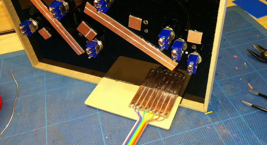 |
|
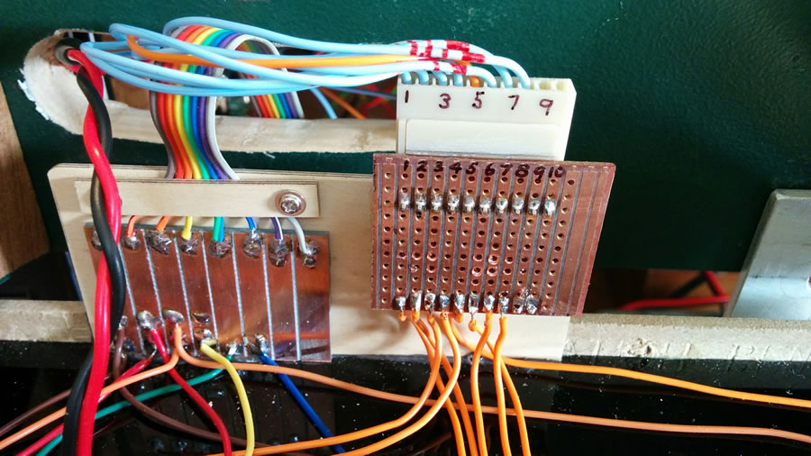
The PCB here brings in the connections from the module that controls the point switches shown in the first photo. The connecting cable is called "rainbow cable" and sells from suppliers like Jaycar in 16 wire ribbons. Other suppliers have even wider cables but they all repeat in batches of 10. This cable makes figuring out which wires go were much easier. |
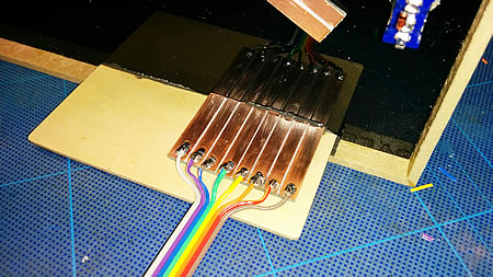 |
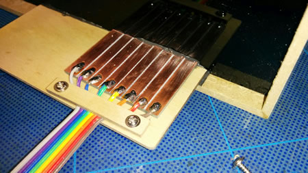
Strain relief on the cable is provided by clamping an additional piece of 2mm plywood. The mounting ply and the PCB are epoxied to the recycled picture frame housing the panel. |
 |
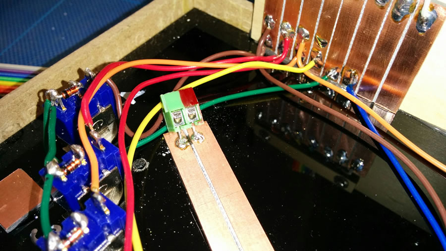
Some wiring is in place and a screw terminal, normally mounted through a PCB has been attached to the DCC strip board. Drill two 1mm holes at an angle and solder the screw terminal to the top of the PCB. This way the 2 DCC connections can be unscrewed if required. |
|
 |
|
The panel shown above is now complete and ready for testing. At the back, the LH PCB connects switches to the panel. This board was made using techniques shown above. The right hand board is a piece of commercial strip-board sometimes known as Veroboard. This board is bringing in connections to the frog from 8 points. This signal is used to set indicator LEDs showing which track is "set". |
|
 |
|
 |
|
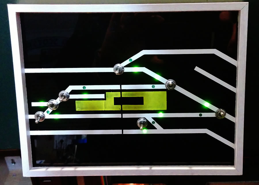
This gives some idea of what the panel does - the LEDs indicate which road is set. The switches also indicate the road but the LED is easier to see and actually indicates that the road has power. The switch on the right is replicated on the next panel and can be controlled from either panel. |
|
 |
|
