Servos for Points (Turnouts) Rick Fletcher - NSW Australia |
Updated 16 July 2016
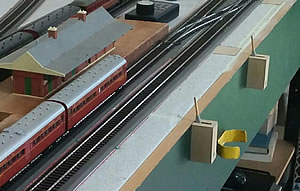
The photo shows the basic setup. The servo is located to the side of the point/ turnout and connected to it with a short "L" shaped wire.
I use 1.2mm steel wire running through a short guide tube. This connects to the servo arm via a "Quick Connector". The servo cable exits under the layout. The guide tube I use is a short piece of bicycle bowden cable outer - used for gear selection from memory. |
|||||
 |
|||||
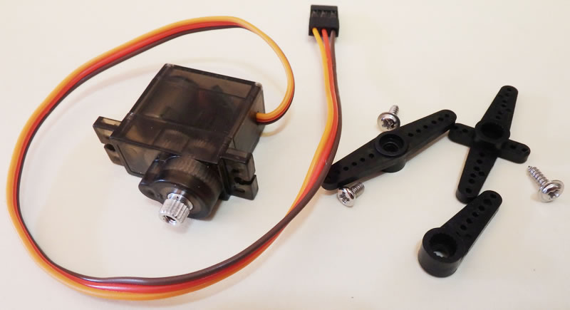
The servos I use are Tower Pro SG90 style or my preference Micro 9g Metal Gear Servo. Shown below is a "Micro 9g Metal Gear Servo For Futaba Hitec HS-55 GWS walkera RC HELICOPTER GA" as described on eBay. Here is a LINK to the eBay site I used but check other sources for a possible better deal. The current cost is $4.87 (16 July 2016) with free postage to Australia. There are cheaper plastic gear models but I have found these ones to work more smoothly and to be much quieter. As you can see, they come with a variety of servo arms and any will work in this application. |
|||||
|
|||||
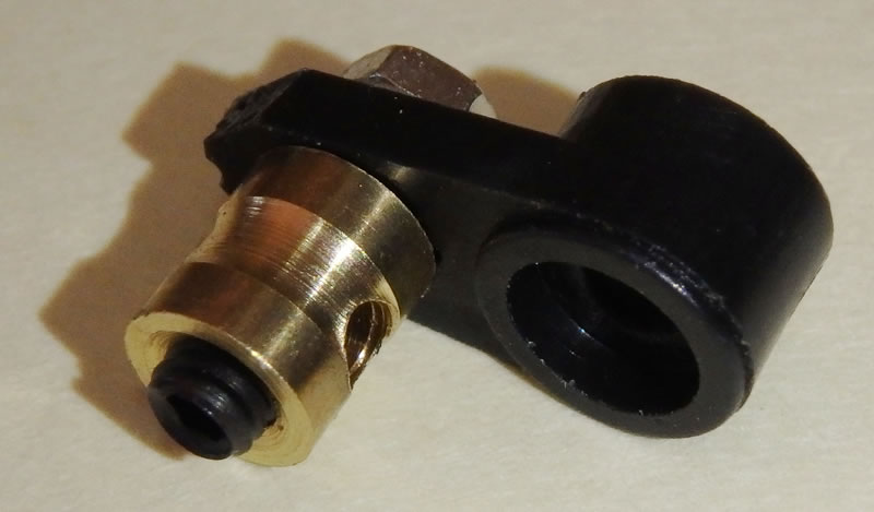
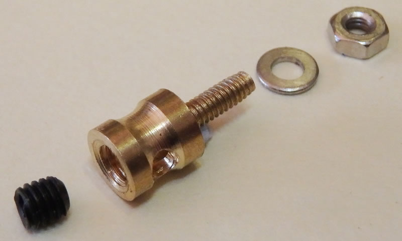
To connect the servo to the point/ turnout a "Servo Quick Connect" (shown below) is very good. I bought a set of 20 for $4.12 !! That's a little over 20c each. They were sold as "Durable 2mm Aircraft Stopper Servo Connectors Connector with Screws Set of 20" and one eBay supplier I used was at this LINK . |
|||||
 |
|||||
| This what you get for about 20c. A beautiful piece of micro engineering. | |||||
 |
|||||
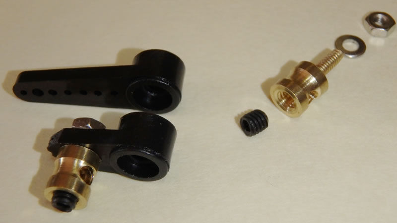
I use any of the servo arms supplied. Select the second hole from the pivot point of the servo arm and drill a 2mm hole in there to take the servo quick-connect. The point needs to move less than 3mm (HO) and initially I went for maximum torque by using the first hole and that is what is shown in the top photo above. That hole is too close to the hub of the servo arm and some fiddly trimming is needed. I discovered that there is no need to use it as there is plenty of torque when using the second hole as shown below. Assembly order is shown for the quick-connect. It needs to be free to rotate in the servo arm and the nut is best secured using a tiny bit of thread locker. The grub screw allows positioning adjustment but the travel and end points need to be set by some electronics. |
|||||
 |
|||||
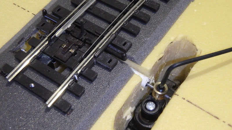
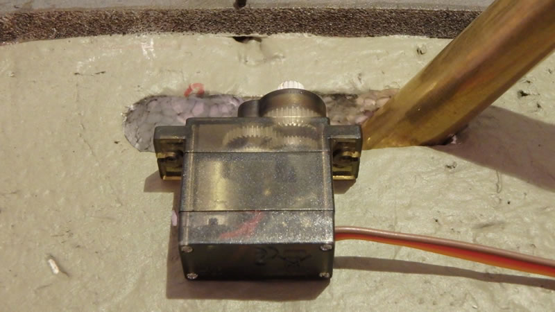
This servo is being retrofitted to a turnout on EPS foam. As the control wire was already in place, an additionally wide access slot was needed to allow the servo to slide in under the wire. |
|||||
 |
|||||
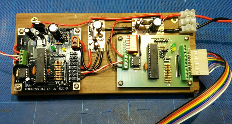
Shown below - 2 boards in use on my layout. The left hand one controls the servos (8) and the right hand one handles the switches controlling the servos operating the points. This system was devised by the MERG group in the UK - see their Website The operating system uses a CAN bus (2 wires) to distribute control events around the layout in a manner similar to that used in modern motor vehicles. |
|||||
 |
|||||
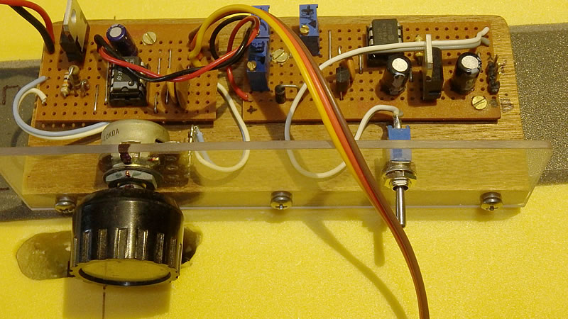
This is a MERG design with the left hand one designed to test servos - in this case I use it to test new servos and to set them to their midpoint. The right hand one is, in effect, a stand alone method of controlling one servo & its point with a switch. The 3 blue components are variable resistors used to control the speed of the servo and distance it moves Left & Right. |
|||||
 |
|||||
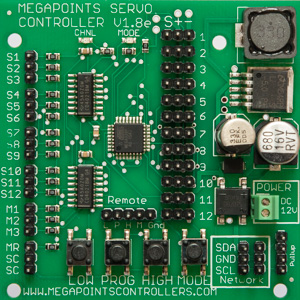
| The device shown below is a " MegaPoints Controller" by a UK company and could be very good for those people not confident in building PCBs themselves. I have not seen it in operation but it comes ready to connect to 12 servos and has 12 corresponding switch inputs. Here is their Website and here is a link to a YouTube Demo There are 2 videos in sequence. Cost is said to be £50 from the UK. | |||||
 |
|||||
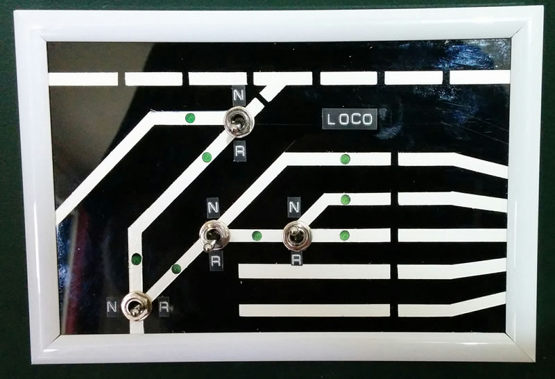
| The end result will be some type of panel with switches where each operates the point/ turnout shown on the diagram below. The beauty of the MERG CANBUS is that a switch on one panel cab control a point anywhere on the layout. Crossovers with 2 points are controlled by one switch. The whole thing can be computerised using JMRI. |
|||||
 |
|||||