Manual Point Operation by Wire in Tube Rick Fletcher - NSW Australia Updated 22 Aug 2016 |
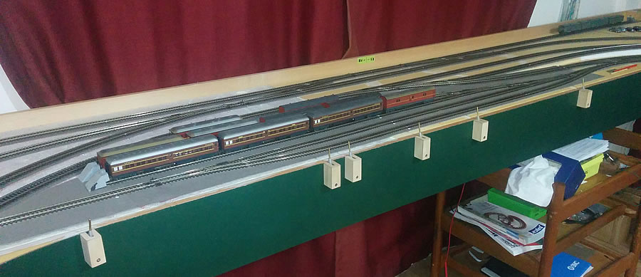
| This section covers the construction and installation of mechanical lever frames which are not prototypical in appearance but do move in a manner not dissimilar to the prototype. Also covered is the associated "Wire in Tube" (WIT) operation and installation. The photo below shows some lever frames in position near the Carriage Works in the early stages of my layout. Four of these control single points and two control facing points (crossovers). On this page "Point" = "Turnout" "Sleeper" = "Tie" |
|||
 |
|||
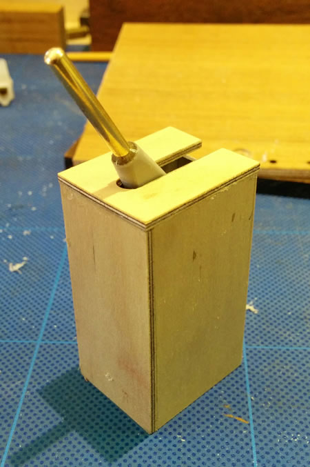
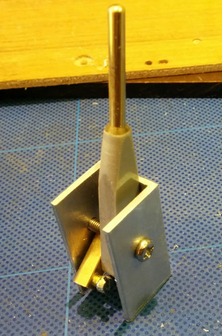
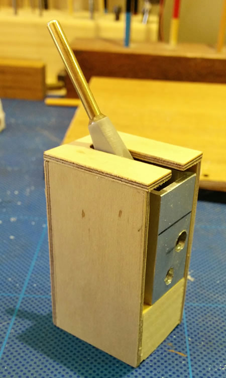
| The lever frames are two assemblies - the frame mechanism itself and the housing. | |||
| The housing was fabricated from 2mm ply and a small block of wood. | The frame is based on a standard aluminium section plus some metric nuts, bolts and screws, an electrical connector, and a PVC and brass welding wire handle. I have some sketches. | ||
 |
 |
||
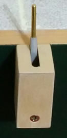
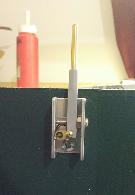
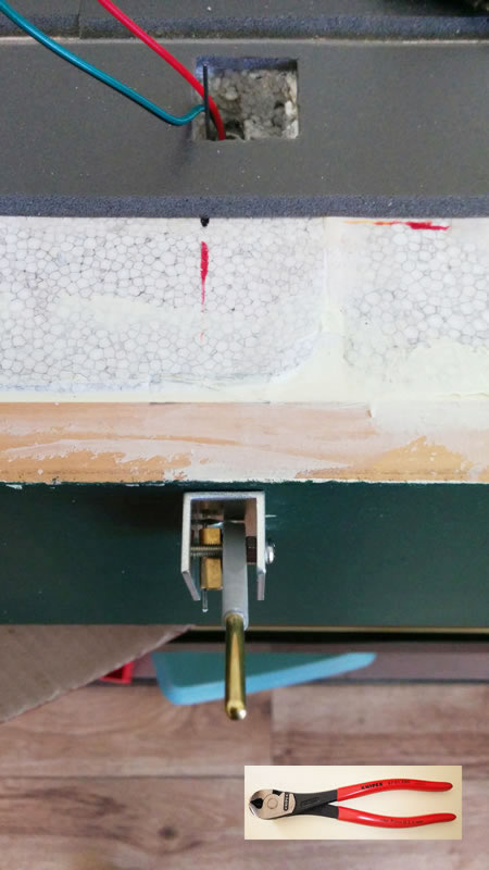
This frame is for a single point |
The aluminium mount is held to the fascia by a single screw through the bottom hole. The top hole receives the WIT. |
||
 |
 |
||
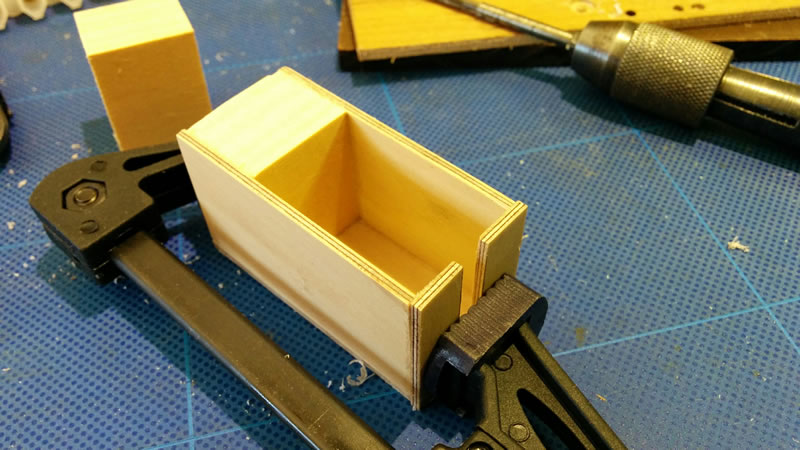
| Test assembly - then glued with PVA | |||
 |
|||
| A single lever frame with the operating wire bent at right angles. I use 1.25mm dia piano wire which needs a powerful hardened cutter as shown at the bottom of the photo below. |
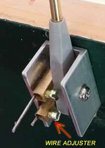
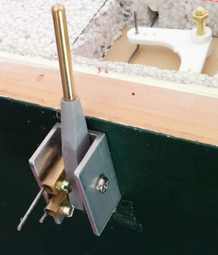
This lever frame has a push pull action which is needed to operate two facing points in a crossover. Because this crossover is so close to the fascia, a pair of bellcranks must be used to operate the point out of picture to the right. | ||
 |
|
||
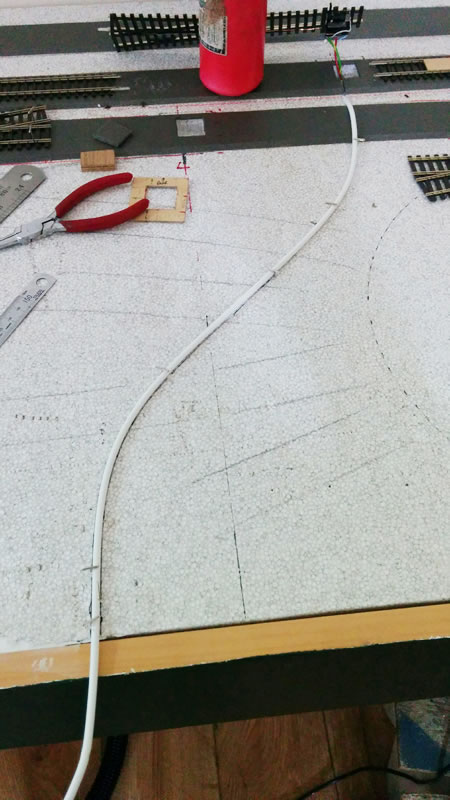
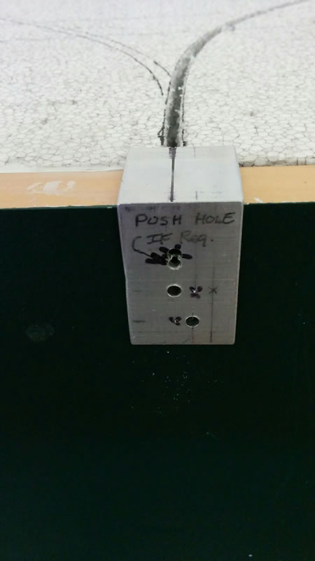
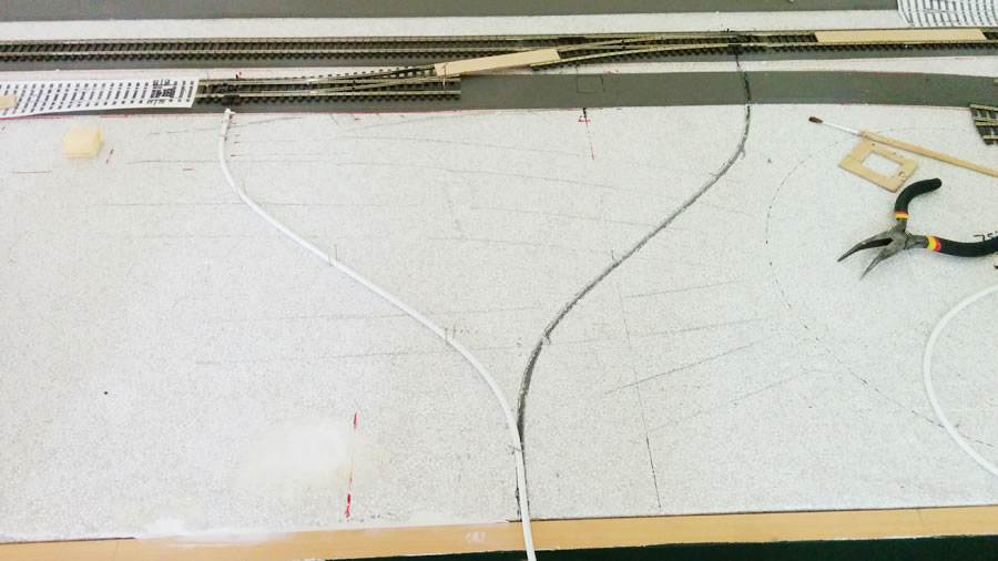
| Showing how the WIT path is laid out to give a smooth curve to the point. The bowden cable is pinned in place with "T" pins (from a Craft shop). The outer casing is from a bicycle shop and is used for gear change cables. The inner is too flexible so a rigid wire must be used, such as piano wire. 1 to 1.25mm is a good size. Cut it with the tool shown above. Draw some lines with a marker pen to record the position of the "trench". | Here is the groove or trench cut for the twin WIT needed for the 2 points in a crossover. One has already been cut - actually routed with a Dremel. The aluminium angle is a template used to drill the Mounting hole (bottom); the single point WIT hole (middle) and the extra hole for the second WIT (top). |
||
 |
 |
||
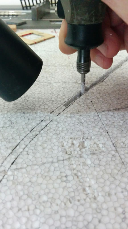
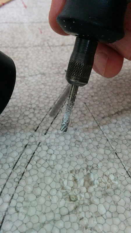
| Using a Dremel tool to cut a groove, here in EPS (Expanded Polystyrene) which is very messy stuff. The black nozzle on the left is a vacuum cleaner which needs to be used. The High speed cutter is 3.1mm dia and the outer WIT cable is 4mm which means that it is a nice tight fit in the groove. | |||
 |
 |
||
| Two runs of WIT for a crossover. One thing to note is that care needs to be taken in having ALL your trackwork laid out as these two had to pass under the trackwork to the turntable. In this case they need to be done first. One is routed, the other being laid out. | |||
 |
|||
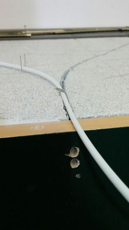
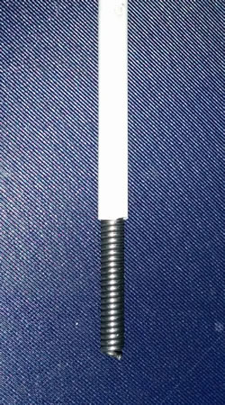
| The 3 fascia holes have been drilled ready for the WIT and the mounting screw. | The outer cable for the WIT setup. The plastic section is 4mm dia. The spiral wound inner section is flexible and slippery for the operating wire. The I.D. of the inner is about 1.6mm. |
||
 |
 |
||
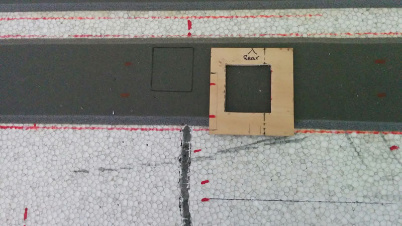
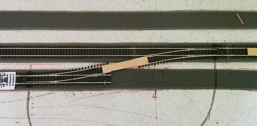
| This template locates the cut-out needed to accept the microswitch under the point. The red lines are used to align it to the rails as the switch is off centre. | |||
 |
|||
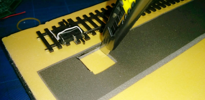
| Having marked out the position of the recess for the microswitch, cut the underlay and foam with a sharp knife. | |||
 |
|||
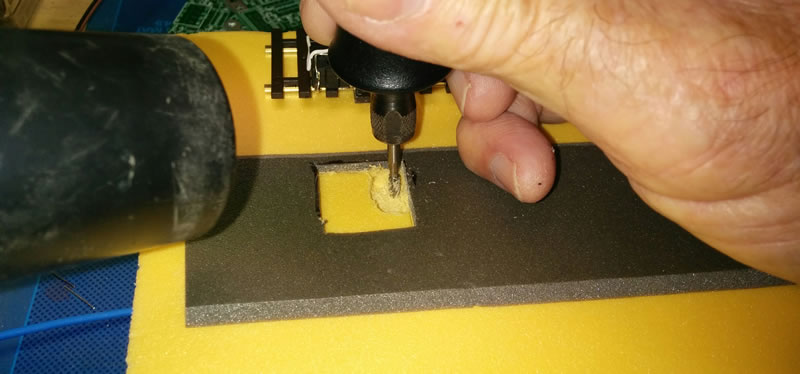
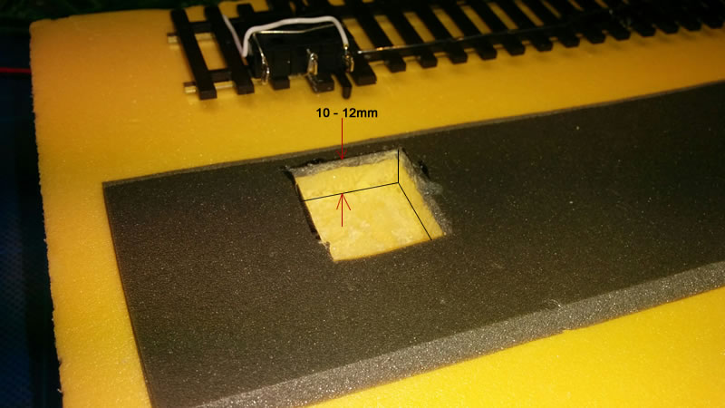
| Routing the hole to a depth of 10-12mm with a Dremel (and vacuum cleaner). | |||
 |
|||
| Ready for a test fit. | |||
 |
|||
| Checking that everything is in alignment. | |||
 |
|||
This assumes that:
|
|||